Purpose
The RT1650 is a wireless power receiver compliant with WPC low power V1.1 standard. This document explains the function and use of the RT1650 Evaluation Board (EVB), and provides information to enable operation, modification of the evaluation board and circuit to suit individual requirements.
Introduction
General Product Information
The RT1650 is a wireless power receiver compliant with WPC low power V1.1 standard. The RT1650 integrates a synchronous full-bridge rectifier, a low dropout regulator, and a Micro Controller Unit (MCU) for control and communication. The device receives AC power from a WPC compatible wireless transmitter and provides output power up to 7.5W, which could be used as a power supply for a charger of mobile or consumer devices.
The MCU-based controller can support bi-direction channel communication including Frequency Shift Keying (FSK) demodulation for power signal from the transmitter and Amplitude Shift Keying (ASK) modulation for power signal to the transmitter. The RT1650 provides Foreign Object Detection (FOD) function to meet the requirement after WPC LP V1.1.
The RT1650 provides a programmable dynamic rectifier voltage control function to improve power efficiency, a programmable current limit for suitable load setting, and proper protection functions such as UVLO, OVP, and OTP.
Product Feature
-
Single-Chip WPC V1.1 Compliant Power Receiver
-
Integrated Synchronous Rectifier Switch
-
Support Output Power up to 7.5W
-
Rectifier Efficiency up to 96%
-
System Efficiency up to 80%
-
Programmable Dynamic Rectifier Voltage Control for Optimized Transient Response and Power Efficiency
-
Embedded 32-bit ARM Cortex-M0 MCU
-
Easy Tuning for Communication and Control Parameters
-
Support Bi-direction Channel Communication
►
FSK Demodulation for Power Signal from Wireless Power Transmitter
►
ASK Modulation for Power Signal to Wireless Power Transmitter
-
Support Alignment with Transmitter
-
Over Current Limit
-
CSP 3.0mm x 3.4mm 48B (Pitch = 0.4mm)
-
Low Profile (0.5mm Max.)
Application
-
WPC Compliant Receivers
-
Cell Phones & Smart Phones
-
Portable Electronic Devices
Specification
|
Parameter
|
Symbol
|
Min
|
Typ
|
Max
|
Unit
|
|
Input Voltage Range
|
VRECT
|
5
|
--
|
10
|
V
|
|
Output Voltage
|
VOUT
|
--
|
5
|
--
|
V
|
|
Output Current
|
IO
|
0
|
--
|
1.5
|
A
|
|
Current Limit
|
ILIM
|
--
|
1.6
|
--
|
A
|
|
Operating Frequency
|
fOSC
|
110
|
--
|
205
|
kHz
|
RT1650 Evaluation Board
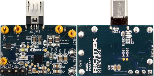
Please carefully inspect the EVB IC and external components, comparing them to the following Bill of Materials, to ensure that all components are installed and undamaged. If any components are missing or damaged during transportation, please contact the distributor or send e-mail to evb_service@richtek.com
Test Points
The EVB is provided with the test points and pin names listed in the table below.
|
Test point/
Pin name
|
Signal
|
Comment (expected waveforms or voltage levels on test points)
|
|
TR1, TR2
|
Input voltage
|
Power input. Connect with standard Qi Rx coil to receive AC power input.
|
|
RECT
|
Rectifier output
|
The rectifier output. Connect 20µF capacitor to GND to reduce the voltage ripple.
|
|
GND
|
Ground
|
Ground.
|
|
OUT
|
LDO output
|
LDO support the 5V/1A output power.
|
|
ADD
|
Adapter input
|
Adapter 5V input. This voltage connect to the OUT directly.
|
Power-up & Measurement Procedure
1. Connect input pin (TR1, TR2) with Qi standard coil.
2. Put the Rx coil on the WPC compatible Tx and let the cooper face to the Tx coil.
3. Waite few seconds for the communication and power up. The LED1 (White LED) is for the vout ready and LED2 (Red LED) is for the vrect ready.
4. Customer can increase the loading to 1A from OUT pin slowly.
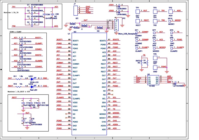
Schematic
Bill of Materials
|
Reference
|
Qty
|
Part number
|
Description
|
Package
|
Manufacture
|
|
U4
|
1
|
RT1650
|
RT1650
|
WL-CSP-48B 3x3.4 (BSC)
|
RICHTEK
|
|
U3
|
1
|
PMDPB80XP
|
dual P-channel MOSFET
|
|
NXP
|
|
U6
|
1
|
C22TCH-05XT-1XBLX
|
Micro-USB Connecter
|
|
Cherng Weel
|
|
C1, C2, C3, C4
|
5
|
0603B473K500
|
47nF/50V/X7R
|
0603
|
WALSIN
|
|
C7, C10
|
2
|
0603B103K500
|
10nF/50V/X7R
|
0603
|
WALSIN
|
|
C8, C11
|
2
|
C1608X7R1H474KT
|
0.47µF/50V/X7R
|
0603
|
TDK
|
|
C9, C12
|
2
|
0603B223K500
|
22nF/50V/X7R
|
0603
|
WALSIN
|
|
C13, C15
|
2
|
GRM31CR71E106KA12L
|
10µF/25V/X7R
|
1206
|
muRata
|
|
C14, C17
|
1
|
C1608X7R1H104KT000N
|
0.1µF/25V/X7R
|
0603
|
TDK
|
|
C16
|
1
|
C2012X7R1E105KT
|
1µF/25V/X7R
|
0805
|
TDK
|
|
C18, C19
|
2
|
C1608X5R1E105KT000E
|
1µF/25V/X5R
|
0603
|
TDK
|
|
C36
|
1
|
0603N101J500
|
100pF/50V/NPO
|
0603
|
WALSIN
|
|
C38
|
1
|
0603B182K500
|
1.8nF/50V/X7R
|
0603
|
WALSIN
|
|
LED1
|
1
|
LNL-190UW-4H
|
LED
|
|
LighTop
|
|
LED2
|
1
|
LNL-191SUR
|
LED
|
|
LighTop
|
|
RNTC1
|
1
|
|
NC
|
0603
|
|
|
RUSB1, RUSB2
|
2
|
|
NC
|
0603
|
|
|
RUSB3
|
1
|
0R
|
0Ω
|
0603
|
|
|
R14
|
1
|
24K
|
24kΩ
|
0603
|
|
|
R15
|
1
|
10K
|
10kΩ
|
0603
|
|
|
R11
|
1
|
1K5
|
1.5kΩ
|
0603
|
|
|
Coil
|
1
|
WR483245-15F5-G
|
12.9µH
|
|
TDK
|
Enable thermal management : RNTC = NCP15WF104F03RC, R14 = 33k
EVB Layout
|
Top Layer
|
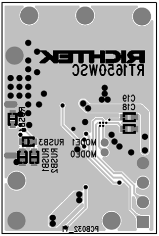
Bottom Layer
|
Operating Guideline
1. Connect receiver coil to TR1 and TR2 pins respectively.
2. Connect positive end and negative end of load to OUT and GND pins respectively.
3. Power on transmitter and place the receiver coil on the surface of transmitter interface.
4. When the receiver output is turned on, the LED will be turned on as an indicator.